Jose L. Agraz, PhD
PZT Linear Motors
PZT Linear Motor : Results
FEM and Experimental results
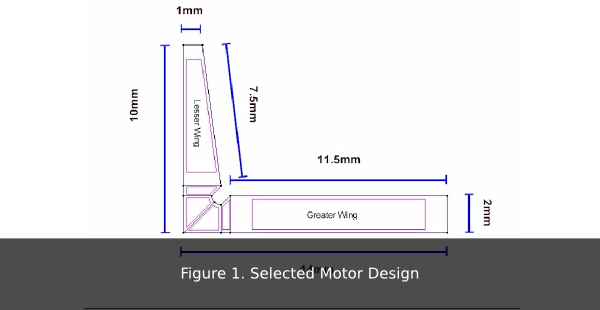
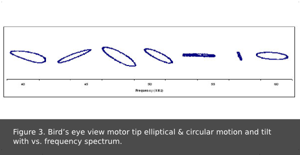
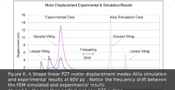
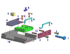
Several methodical designs were built using a pre & postprocessor software GiD version 7.2, and later simulated using Finite Element Method (FEM) Atila software version 5.4.2. A design using a 1mm thick piece of PZT with a Greater Wing of 2x2x14mm and a Lesser Wing of 1x2x10mm was selected Figure 4-1. This design showed the largest elliptical displacement and narrowest bandwidth between the motion displacement peaks of each wing, or lateral and forward motion modes. X, Y, & Z clamp conditions were applied at the far end of each wing holding the motor in place. Single phase power to the Greater Wing computer simulations yielded a forward motion displacement peak of 14μm at 67kHz and a lateral motion displacement peak of 5μm at 71kHz, resulting in a 4kHz bandwidth between motion modes at 60 V pp Figure 8. Furthermore, the motor elicited a full range of tilt of the ellipse relative to the x-axis from 0 to 180o Figure 3.
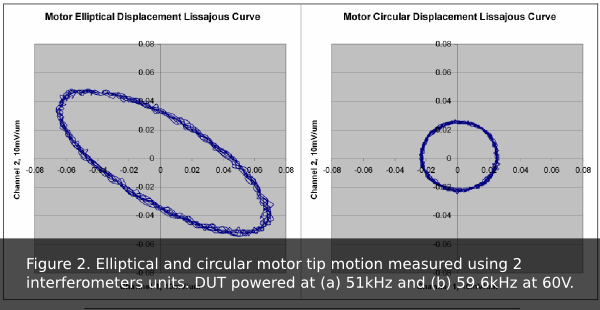
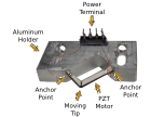
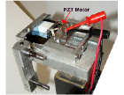
The device was mounted on an aluminum holder Figure 7 and characterized for displacement, motion, and mode shape. Measurements were made using two Polytec FV3001 vibrometer controllers and OFV511 Fiber interferometers, arranged 90o with respect to each other, and focused on the tip of the motor. The displacement Lissajous curve values were captured using a 54645A Tektronix Oscilloscope. Single phase power to the Greater Wing experimental measurements elicited a forward motion displacement peak of 13μm at 53.8kHz, and lateral motion displacement peak of 5μm at 50.3kHz, resulting in a 3.5kHz bandwidth between motion modes at 60 V pp Figure 6. The experimental results values were found at a lower frequency because of motor dimensions errors introduced when cutting the PZT material using a large blade wet saw during manufacturing.
Motor Drive Optimization
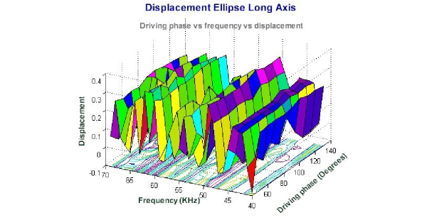
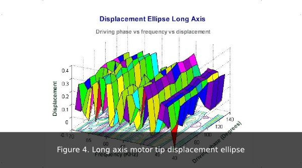
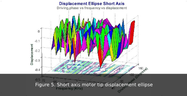
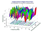
Motor optimization was done by measuring the displacement along the x-y axis at the motor tip while varying the driving frequency and the phase shift between the Greater and Lesser Wing. However, the measurements were automated using LabView software controlling the vibrometers through the General Purpose Interface Bus (GPIB) port. The data gathered was later plotted by wing using Microsoft Excel. The Long Figure 4 and the Short Figure 5 axis yielded an optimized frequency of 48Hz at a 100° phase shift with respect to the other wing.
Motor Load Characterization
The motor load characteristics were tested by utilizing a simple concept of measuring time at a given displacement of the load with respect to the amount of weight being lifted by the system.
A 20mm long glass intermediary load was placed on a silicon wafer surface to minimize friction. An unloaded motor tip was set to an elliptical motion with an axial ratio (AR) of 8/7 at 51.4 kHz, and placed at the beginning of the 20mm intermediary load. Next, the motor was powered up using a single phase fashion on the Greater Wing, and the elapsed time for the motor to move the load from end to end was recorded for different weights. The system produced an average linear motion of 9 mm/s for a load of 2.6 grams at 60V pp single phase.
Results Discussion
This new linear motor design elicited approximately 15% displacement deviation results between experimental and FEM simulations for driving the motor in single phase mode (Greater Wing only), but two phase power applied to both wings may yield even better results. In addition, this motor design produced an average linear motion of 9 mm/s for a load of 2.6 grams at 60V pp single phase mode. However, motor dimension errors introduced during wet saw cutting Figure 1, electrode spacing at the tip, and motor tip wear and tear of the bulk PZT material, elicited resonant frequency shifts between FEM simulations and experimental results. Furthermore, the fast wear and tear at the motor’s tip and the followed grooves formed by the electrodes on the load Figure 2, made accurate thrust measurements impossible.
Recommendations
Although, this motor design is simple, inexpensive, and compact, there are a few
issues that require further research:
1. Limited applied power. Load displacement is proportional to the amount
of power applied to the wings. However, placing the silver electrodes at
such close proximities limits the power fed to the motor due to current
arching Figure 5-3 . A dielectric coating across the motor will isolate the
electrodes effectively beyond a few kilovolts. This dielectric material is
readily available as it is commonly used in magneto wire coating. The
dielectric comes in different voltage ratings and is sold by companies such
as Condumex.
Load displacement by friction. Linear motors inherently produce
displacement by friction. However, direct contact between the PZT
material and the load greatly impacts the motor’s life span Figure 4 . As
the PZT material is much softer than the load material, the sharp PZT
motor tip quickly degrades to a much rounded tip, limiting load
displacement. This problem might be resolved by coating the motor tip
with a harder material such as DOW silver electrode ink.
The design requires the cutting of bulk PZT material. However, the
necessary wet saw equipment available is not capable of tenths of
millimeter accuracy, thus, motor dimension repeatability is extremely
poor. A much more accurate process is necessary, such as tape casting.
4. Displacement direction. The power applied to the motor wings is applied
at a random phase, making the motor tip rotate clockwise or counter
clockwise. However, the development of a drive circuit based on a Field
Programmable Analog Array (FPAA) and a high voltage Operational
Amplifier will allow for control and accuracy of the power delivery to
the motor.
5. Time consuming motor characterization. Depending on the application,
there are an infinite number of frequencies the motor could operate at, but
manually exploring a 50 KHz spectrum is an overwhelming task.
However, the development of an Automatic Test Equipment (ATE) setup
will greatly increase productivity and repeatability.
Future Work
There are two main issues that require more research work; motor dimension repeatability and motor characterization setup.
Motor Construction Accuracy & Repeatability
Cutting and trimming bulk PZT material is very cumbersome as a wet saw is necessary. During cutting, accuracy is highly dependent on cutting speed, blade stability, and cooling. In addition, fine trimming the motor usually led to the PZT material cracking and eventually breaking up, resulting in a low yield of 10:1.
Tape Casting Method
Tape casting have the potential of avoiding accuracy and repeatability issues , since punching a sheet of unsintered PZT tape is accurate, fast, and a mature process. Preliminary tape cast process results showed that repeatability and yield (5:4) were much higher than using bulk PZT.
Sandwiched Core Method
A sandwiched core is another alternative approach to building Λ shaped linear motors. This approach would potentially solve the two biggest problems; wear and tear of the motor’s tip and the PZT material cutting. This method involves the realization of a metal core using micromachining and placing PZT slabs on top and bottom of the core . Since producing PZT slab is relatively simple and a metal core would alleviate the wear and tear of the motor’s tip to some degree, this approach merits further study.
Characterization Setup Fixture Improvements
The motor characterization setup is the most basic and most important element in the development of this motor. A characterization setup that is more stable and that minimizes load drag, as well as a setup that allows for 3-D load motion will produce better measurements.
 Introduction
 Literature
 Methods
 Results
Feb 14th, 2015 at 5:09 pm