Jose L. Agraz, PhD
PZT Linear Motor
PZT Linear Motor: Literature Review

Piezoelectric Materials Background
The piezoelectric effect is a property that exists in many materials. The name
combines the word “piezo” or Greek for pressure, and “electric”, or Greek for amber.
Piezoelectric material converts electrical to mechanical energy and vice versa. As a result
of an electric field E, piezoelectric material produces three different deformation modes;
d 33 , d 31 , and d 15.
The d 33 and d 31 modes take place when the applied electric field is in the same
direction as the poling direction. Poling is achieved by subjecting the material to a DC
voltage across the material, causing permanent dipole alignment in the material.
However, the quality of domains is proportional to voltage amplitude, exposure time, and
temperature. The applied field is parallel to the poling direction. By convention, the 3
direction is parallel to the poling direction and the 1 and 2 directions are perpendicular to
it.
When an electric field is perpendicular to the poling direction, shear strain occurs,
the d 15 mode. The shear is in the plane created by the poling and applied electric field
vectors (1 and 3). In most piezoelectric materials, d 15 is the largest piezoelectric
coefficient.
Piezoelectric Motors
Ultrasonic motors are defined as devices that utilize vibration in the ultrasonic
range to generate motion. This motion is the result of the contraction and expansion of
the PZT ceramic elements. However, the contraction and expansion, or displacement is
very small (about 1μm), but by supplying power at resonance frequencies, the
displacement may be considerably larger, thus, making the PZT elements capable of
thrust.
Piezoelectric motors are categorized in two types: Rotary and linear type.
Each of these two types of ultrasonic motors benefits from characteristic electromagnetic
motors may lack, such as; high torque densities at low speeds, fast response, self locking,
flexibility, and flexibility in structural design. These characteristics make ultrasonic
motors a genuine contender for high resolution and long travel intermittence motion
generating purposes.
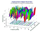
Linear Piezoelectric Definition
Linear motors or traveling wave motors generate motion by combining standing waves on two or more pieces of PZT material. These standing waves share the same frequency, but are 1⁄4 wave length out of phase. The generated traveling wave in turn produces an elliptical displacement which generates motion by friction between PZT pieces.
Kurosawa Motor
The Kurosawa motor is the closest design that resembles this project’s objective. The motor consists of two sandwiched type vibrators, arranged as a bolt-clamped Langevin transducer setup. The vibrators cross at right angles and operate on two vibration modes; symmetrical (normal motion) and anti-symmetrical (lateral motion) mode, both are driven a resonance and with a 90o phase shift with respect to each other. However, the design requires heat treated high strength chromium manganese steel bolts binding the PZT material, and a Zirconia ceramics plate at the tip as a frictional material. Although, the motor produces high speeds and thrusts, the motor is large, complex, and difficult to miniaturize.
Kyongjai Motor
The design consists of the shaking of a beam by two actuators resembling the
letter “π”, producing an elliptical displacement at the tip located at the mid
point of the beam.
The displacement is produced by actuators generating longitudinal and flexural
motion being powered at resonance and 90o out of phase with respect to each other. The
amplitude of the displacement is dependent of the power applied, frequency, and load
pressure. In addition, the speed of the load is dependent on friction between the load and
the driving, and the displacement amplitude at the motor’s tip. Although, the motor
is easy to miniaturize, the motor is complex and requires a dual source of power.
Mozair Linear Motor
This motor was developed by the Ecole Polytechnique Federale De Lausanne (EPFL) in Switzerland and little literature other than a picture is available. The motor is composed of two layered PZT actuators at a right angle driven π/2 out of phase. The tip is composed of a brass 90o junction with square opening fitting the PZT actuators. Although, the motor is simple, the motor is difficult to miniaturize and requires a dual source of power.
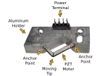
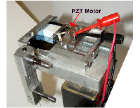
PI Linear Motor
This design is the closest to the Λ shape motor. However, the main difference is
that the PZT actuators are actually blocks transmitting a traveling wave to a hardy tip of
metal located between the two actuators.
Displacement is produced by two rectangular pieces of PZT material, each
alternating to change thrust direction. Although, only one PZT element is excited at a
time while the other remains passive, two standing waves are produced, resulting in a
traveling wave. Thrust is generated at an alumina tip placed at the junction of the two
PZT blocks. Thrust is amplified by preloading a friction bar mounted on the moving
portion of the translation stage. Although, the motor produces large thrust, the motor is
difficult to miniaturize and lacks two dimensional capabilities
 Introduction
 Literature
 Methods
 Results
Feb 14th, 2015 at 5:09 pm